| Some views of a Sienna as it is assembled | These pictures were taken by our builder-for-hire, Alan Wilcox, and DZKit staff |
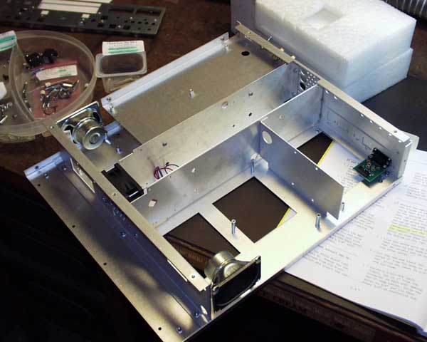 |
Here, seven of the eleven pieces of the chassis have been assembled. Note the small PC board attached to the back panel. This is an RS-232 interface board that connects to the internal controller.
Also note the internal fan in the center compartment. This fan draws air in from the front panel/controller compartment, providing cooling air for the direct digital synthesis chips and vacuum fluorescent display. It exhausts through the center transmitter compartment, providing cooling for the 10W finals. Airflow in the Sienna has been engineered, not added as an afterthought. Also note the large openings on the bottom. These openings provide bottom access to the snap-in IF filters. Finally, note the stereo 1.5W speakers, which provide plenty of volume. Photo courtesy of Alan Wilcox. [ assembly time: 2.5 hrs ] |
 |
This board contains DC power conditioning and distribution. When you add the transmitter you also add the SWR/power meter. This board also holds the optional antenna tuner. Sienna has reverse polarity, overvoltage, undervoltage and overcurrent protection. Resettable fuses protect the main rig and PC. A back panel accessible fuse protects the 100W amplifier. 8-Amp Panasonic relays are used in the tuner and for antenna switching. Two relays are used for antenna switching, one for A and one for B, providing better isolation than some rigs. The SWR/power meter has two ranges, one for 0-10W and one for 0-100W operation. The tuner option has not been installed on this board. When you buy the tuner, the diagonal wire is removed and the additional parts are added to the board. Photo courtesy of Alan Wilcox. [ assembly time: 5.2 hrs ] |
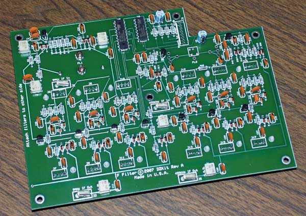 |
The receiver compartment has three stacked boards. This one is mounted on the bottom, and is the IF filter board. The filters, Inrad and/or Collins filters, snap in from the bottom. Four 50-ohm RF cables attach this board to the receiver. Filter isolation, passband flatness and skirts are excellent and very close to the ideal as shown in Inrad measurements of the filters at the Inrad web site. Inrad and Collins filters mount on Yaesu FT-1000 style "C" boards.
The S-100 and SF-100 models (receiver-only) include one 4-pole Inrad 2.4kHz SSB filter at the 9MHz IF and one 20kHz ceramic filter at the 455kHz IF. Many more choices are available - see www.inrad.com for details. Photo courtesy of Alan Wilcox [ assembly time: 4 hrs ] |
 |
This is the receive bandpass filter, preamp and attenuator board, which is the middle board in the three-board receiver stack. Eleven pre-assembled snap-in bandpass filters are provided. These filters are switched in and out via the pre-loaded GaAsFET switches (in this photo, the small pre-loaded ICs located just above and below the filters). These filters can be bypassed via a menu selection to help extract the last dB of weak signal on a fading band. We call it PassiveSignalBoostTM (PSBTM).
Note the switch on the left side. This is a calibration aid. During calibration, you feed the transmitter's BFO signal to the main antenna input on this board, and an on-board attenuator reduces the amplitude to 50uV to allow you to cal the S-meter. (The transmitter oscillators are present all the time, even on the S-100 and SF-100.) Two 10dB RF preamps and two 10dB RF attenuators are also present on this board. Photo courtesy of Alan Wilcox. [ assembly time: 4.4 hrs ] |
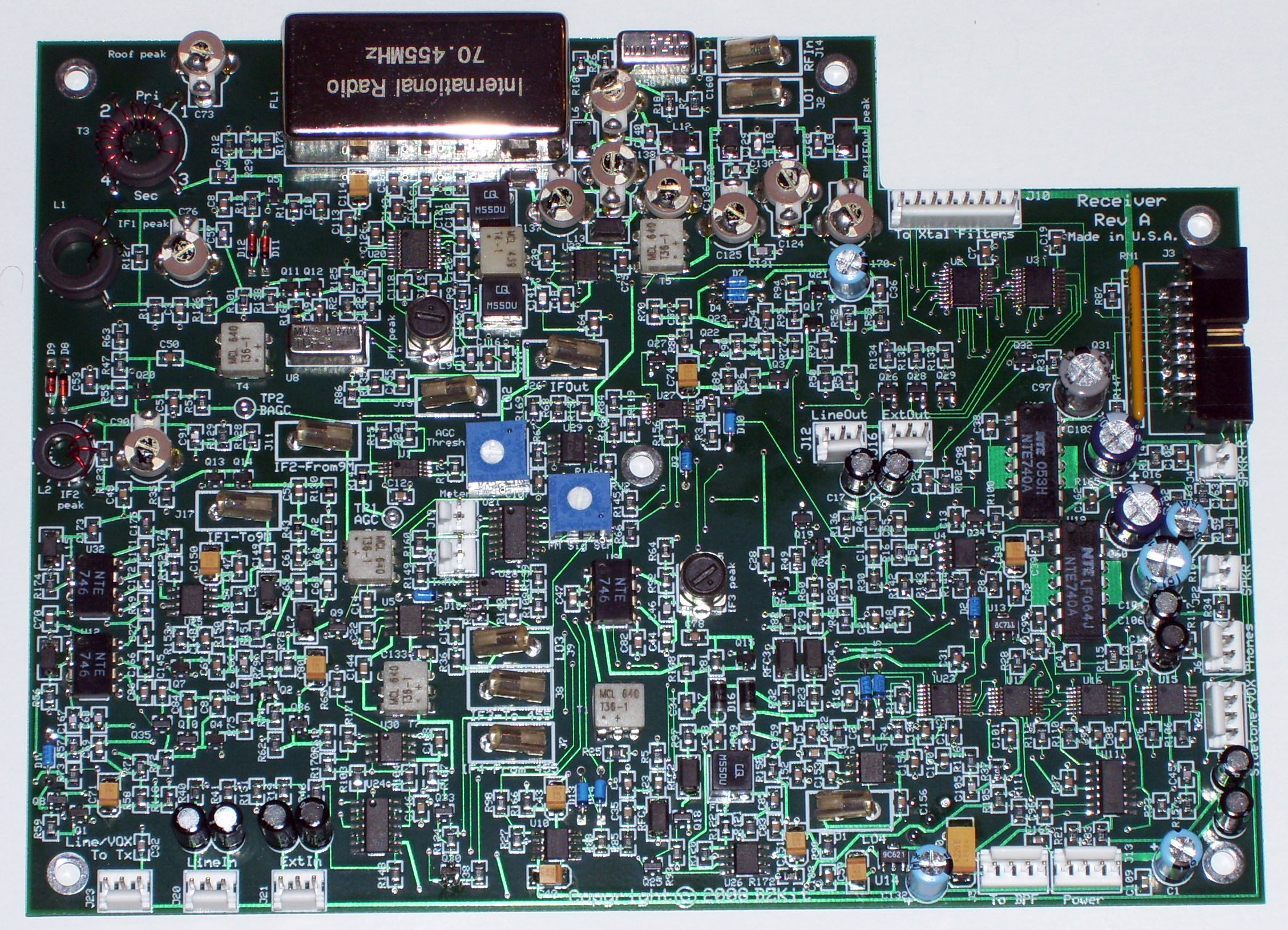 |
The top board in the receiver stack is the receiver itself: a triple conversion SSB/CW/AM receiver with an integrated mixer/FM receiver chip providing a separate path for FM receive and wideband 455kHz IF output. A 4-pole 70.000MHz 15kHz crystal roofing filter is included standard, upgradeable to a high-performance Inrad 4.5kHz 6-pole 70.455MHz roofing filter (shown). A high performance noise blanker with 3 pulse widths and variable threshold is also present. Finally, stereo audio, with a multi-input audio mixer rounds out this board. All surface-mount parts are pre-loaded, so don't let the density of this board scare you! There are about 100 non-SMT parts that you add.
[ assembly time: 3.9 hrs ] |
|
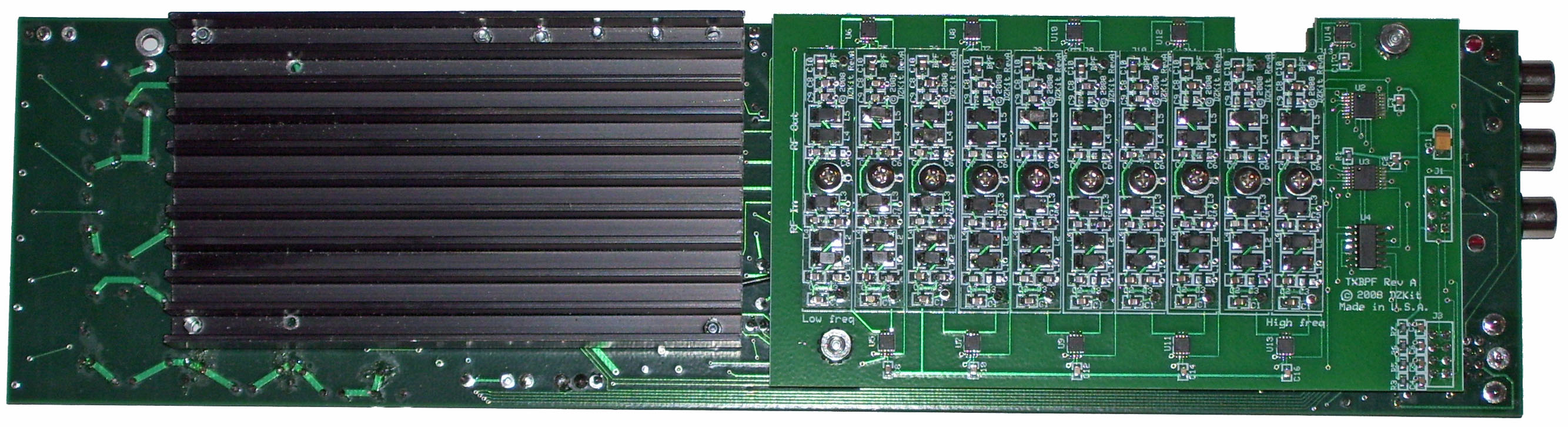
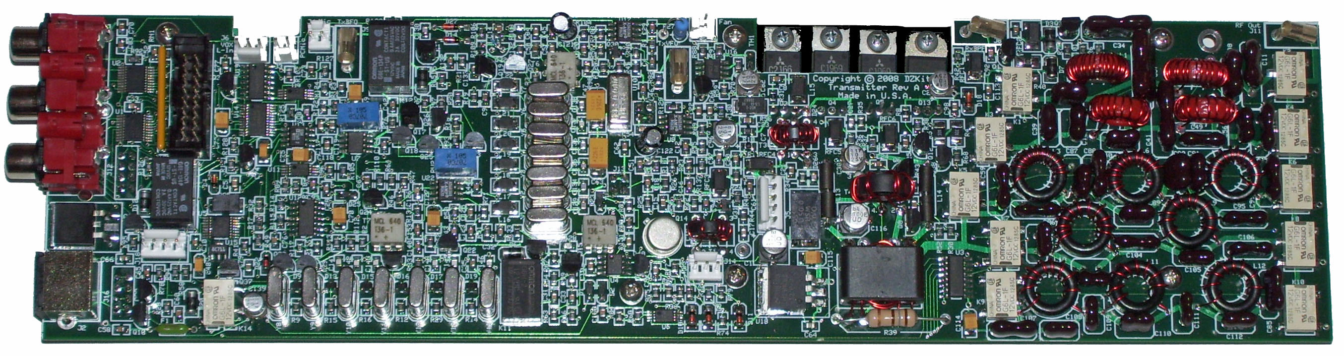
The transmitter board is a single conversion SSB/CW/AM/FM transmitter with 10W finals. Also present here is a variable compression RF speech processor. A 7-element Chebyshev variable bandwidth SSB filter and a fixed 6kHz AM crystal filter are used in the IF. The transmitter's partially pre-assembled bandpass filters and heatsink for the finals are attached to the back of this board. This board operates completely independently of the receiver, allowing full duplex operation, very useful for satellite work. All small surface-mount parts are pre-loaded, so don't let the density of this board scare you!
[ assembly time: 12 hrs ] |
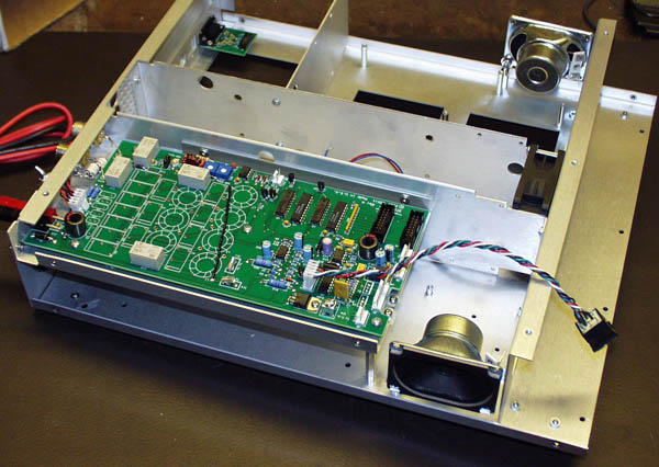 |
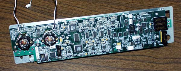
Here, the DCD/Tuner board has been installed in the chassis. At this point, the Sienna is ready to be turned on and the internal power supply voltage regulators checked. Note the gas discharge tubes attached directly to the antenna connectors. These are one of many protective devices to keep your Sienna working fine in less than ideal circumstances.
Photo courtesy of Alan Wilcox [ assembly/test time: 0.9 hr ] |
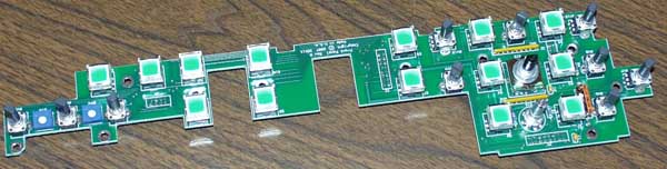  |
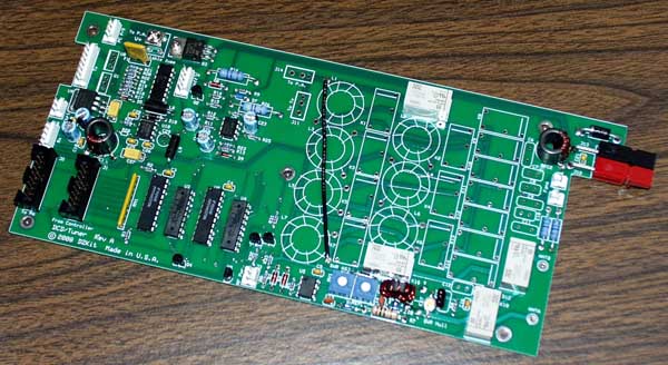
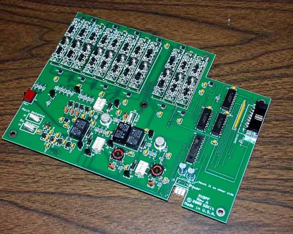
If you purchased the front panel, the next step is to build the front panel PC board and attach it with the display, meters and pre-assembled controller to the front panel sheet metal. If you did not buy the front panel, you still must install the controller to the blank front panel sheet metal.
Photo courtesy of Alan Wilcox [ assembly time: 4.5 hr ] |
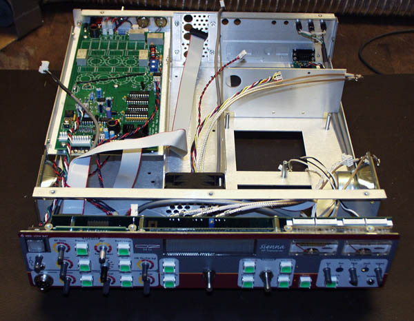 |
The next step is to attach cables to the front panel assembly, attach the front panel assembly to the chassis and turn it on. If you have purchased the full front panel (shown), you can experiment with the controls. In either case you can communicate with an external PC via RS-232. This step-by-step process helps you build confidence that you're doing it right!
Photo courtesy of Alan Wilcox [ assembly time: 4.2 hr ] |
 |
Now it's time to start putting some RF boards in the Sienna. The IF filter board mounts on the bottom of the stack, with IF filters snapped in from the bottom. A special test board connects to the board to verify its operation before you stack the next one on top.
Photo courtesy of Alan Wilcox [ assembly time: 0.5 hr ] |
 |
Once the IF filter board is mounted, the bandpass filter/preamp board stacks on top. A special test board connects to the board to verify its operation before you stack the next one on top.
Photo courtesy of Alan Wilcox [ assembly time: 0.5 hr ] |
 |
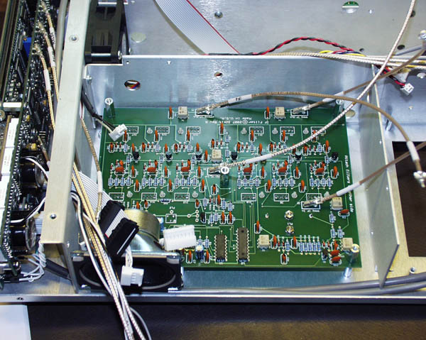
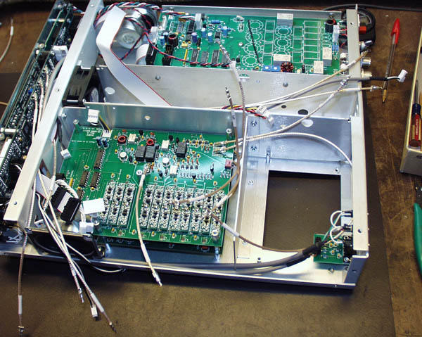
The final step of receiver integration is to stack the receiver board on the other two and connect cables. You're now ready to turn on and calibrate the receiver using the transmitter's BFO as a calibrated frequency source. The S-meter (either the one on the front panel or the value displayed on the PC's rig control software, or using a voltmeter to the S-meter terminals) is used as a relative signal strength meter during cal. Screwdriver adjustments are made according to a simple procedure, using just an external voltmeter. Since the speakers are now active, you can also experiment with the keyer (included even with the S-100/SF-100 receiver!). Note the use of high-quality MIL-SPEC M17/113-RG316 50-ohm cable to interconnect the RF and IF sections of the boards. These cables are pre-assembled and labeled for easy integration.
Photo courtesy of Alan Wilcox [ assembly time: 2.2 hr ] |
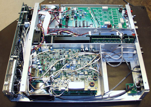 |
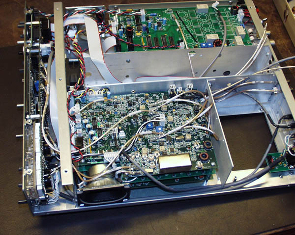
If you purchased the transmitter, it is inserted into the center compartment and the cables connected. There are only two steps to transmitter calibration -- carrier null and RF power calibration, both very straightforward. Then just place the cover on the unit, attach the knobs (if you purchased the front panel) and you're ready to operate!
If you purchased the 100W amplifier, that's the next step. The amp slides into the compartment beneath the tuner/dcd board. Photo courtesy of Alan Wilcox [ assembly time: 1.4 hr ] |